Failures and accidents caused by static in dangerous atmospheres not only can result in physical loss but also place people in danger. At facilities where flammable or explosive substances are handled, static-related safety measures applied in working and production processes are essential for maintaining product quality and preventing fire and explosions. This static eliminator eliminates static generated from processes in dangerous atmospheres by ionizing the air with the safe corona discharge method and thus neutralizing charged objects. The unit offers a special explosion-proof structure based on the Guidelines on Prevention of Explosion of Electrical Equipment of Plants and Factories. Its power supply device also has a built-in protective circuit that detects abnormalities.
(National certificates verifying explosion proofing were obtained in Japan, China and Taiwan, and are pending in South Korea.)
Features
-
AC-type units that eliminate static by generating ions
-
The units apply the corona discharge method, which enables them to eliminate static without contacting the charged object.
-
The static eliminating electrode features a completely new structure that uses a ceramic dielectric element for capacitive coupling.
-
The static eliminating electrode uses chemical-resistant materials (such as toluene).
-
The high-voltage power supply device comes with a built-in protective circuit that shuts down the device and signals an alarm with a lamp and buzzer when it detects abnormal discharge of the static eliminating electrode or the high-voltage line, or abnormality of output voltage.
-
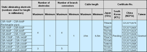
One high-voltage power supply device permits use of up to four static-eliminating electrodes and four branch connectors. The maximum length of the high-voltage cable is 31 meters including the electrode lead cable.
Special explosion-proof structure
Special explosion-proof structure is an explosion-proofing structure apart from the intrinsically safe, pressure-resistant, oil-immersed, pressurized, and increased safety explosion-proof structures, and was confirmed by an official body as preventing explosive gases from igniting.
● Explosion class: 1 ● Ignition temperature: G4 ● Standard environmental condition of explosion-proof electrical equipment: up to 1,000 m above sea level
Specifications
High-voltage power supply device
|
Model |
PAS-701S |
|
Rated output voltage |
AC7kV (at rated load) |
|
Load capacity |
Maximum: Three CSR-2600P electrodes and high-voltage cable that is 31-m long
Minimum: One CSR-150P electrode and high-voltage cable that is 6.5-m long |
|
Output short-circuit current |
5.2mA |
|
Protective circuit |
A built-in alarm circuit that detects abnormal discharge and output voltage fluctuation |
|
Input power |
AC100V (tap changer for switching to 110V, 200V or 220V) |
|
Frequency |
60 Hz (switched to 50 Hz internally) |
|
Power consumption |
Approx. 50VA |
|
Operating environment |
Temperature: 0°C-40°C, Humidity: 35%-75% RH (no condensation) |
|
Insulation type |
E |
|
Installation location |
To be installed in a non-hazardous location |
Static-eliminating electrode
|
Model |
CSR |
|
Ion generation method |
AC corona discharge |
|
Applied voltage |
AC7kV |
|
Electrode length |
150 mm-2,600 mm (CSR-150P to CSR-2600P)
Variable in steps of 50 mm within the above range. |
|
Effective static elimination current |
0.4 μA/cm or above
(at an installation distance of 20 mm and a charge potential of -5 kV) |
|
Installation distance |
20 - 100mm
(The distance must be within the above range and determined by measuring the potential after static elimination.) |
|
Operating environment |
Temperature: 0°C-40°C, Humidity: 35%-75% RH (no condensation) |
|
Installation site |
To be installed in a hazardous location |
Branch connector
|
Model |
SD-4 |
|
Type |
For two-way, three-way or four-way connection |
|
Connection method |
Metal connector |
|
Applied voltage |
AC7kV |
|
Operating environment |
Temperature: 0°C-40°C, Humidity: 35%-75% RH (no condensation) |
|
Installation site |
To be installed in a hazardous location |
Electrode specifications

* The length of the electrode is variable in steps of 50 mm. Specify the length at the time of the order.
* The electrodes are available only in a single length.
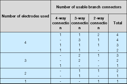
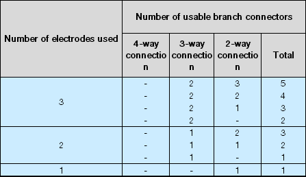
Available combinations of numbers of electrodes used and numbers of branch connectors
CSR-150P - CSR-2000P

CSR-2050P - CSR-2600P

* Only the above combinations comply with the specifications of the certified product. No other combination is permitted.
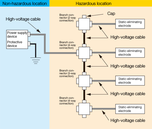
System installation diagram

Dimensions [mm] and names of parts